


The knock sensor threads into the cylinder block. The knock sensor is designed to detect engine vibration that is caused by detonation. When the knock sensor detects a knock in one of the cylinders, it sends an input signal to the PCM. In response, the PCM retards ignition timing for all cylinders by a scheduled amount.
Knock sensors contain a piezoelectric material that constantly vibrates and sends an input voltage (signal) to the PCM while the engine operates. As the intensity of the crystals vibration increases, the knock sensor output voltage also increases.
The voltage signal produced by the knock sensor increases with the amplitude of vibration. The PCM receives as an input the knock sensor voltage signal. If the signal rises above a predetermined level, the PCM will store that value in memory and retard ignition timing to reduce engine knock. If the knock sensor voltage exceeds a preset value, the PCM retards ignition timing for all cylinders. It is not a selective cylinder retard. The PCM ignores knock sensor input during engine idle conditions. Once the engine speed exceeds a specified value, knock retard is allowed.
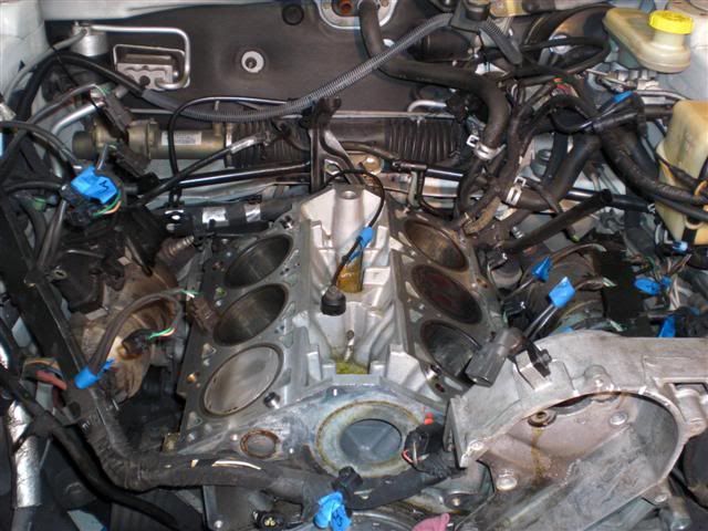
- The sensors screw into the cylinder block , directly below the intake manifold.
- Remove intake manifold plenum
- Disconnect electrical connector from knock sensor.
- Use a crowfoot socket to remove the knock sensors.
To install:
- Install knock sensor. Tighten knock sensor to 10 Nm (7 ft. lbs.) torque. Over or under tightening effects knock sensor performance resulting in possible improper spark control.
- Attach electrical connector to knock sensor.
- Install intake manifold plenum.
---------------

Here is the passenger side as well:

Well, I took the harness and layed it ontop of the harness still on the engine.
Here is the harness laying on the engine:

Everything lines up except for the knock sensors, and the TPS...
The grey plug is the knock sensor connector:


No comments:
Post a Comment