@

max

Wednesday

how to disassemble Dyson DC07 purple vacuum cleaner unit?

Dyson has designed the DC07 vacuum cleaner with simple push-button, clip and tab lock releases for the main removable parts of the vacuum, including the stair, brush, crevice, floor and animal turbo, wand, hose, U-bend pipe, dustbin, post-filter and pre-filter attachments. As a result, to disassemble your machine to clean it, box it for a move or storage, or for simple repairs, all that you need to do is locate the button, clip or tab that locks the piece in place, unlock the piece and remove it from your vacuum.

  • Shut off your Dyson DC07 vacuum by pressing the "On/Off" switch. Unplug the vacuum from the electrical socket.

  • Remove the attachments from your vacuum. Set the pieces aside.

  • Press the quick-draw hose/wand release button and pull up on the handle to unlock the wand and hose from the machine.

  • Hold the wand in one hand and push the wand release button near where it attaches to the hose with the other hand. Pull the wand from the hose. Set the wand aside.

  • Fold the hose down near where it attaches inside the guides at the back of your machine to expose the hose locking tab. Press the tab toward the hose to unlock the hose from the base. Pull the hose from the machine and set it aside.

  • Turn the vacuum around so the back faces you. Lean the vacuum forward slightly so you can see the U-bend pipe. Press the U-bend clip release, pull the U-bend from the vacuum and set the piece aside.

  • Push the clear dustbin release button. Pull the bin from your machine. Empty the bin and then set it aside.

  • Pull the post-filter from the base of the dustbin cavity. Seal it in a clean plastic bag. Set it aside.

  • Look for the pre-filter release button on the top left side of the base of your vacuum near where the dustbin attached to the machine. Push it to unlock the pre-filter and its housing from the machine. Pull the filter and housing from the vacuum and seal the assembled pieces in a plastic bag, or remove the filter from its housing, seal it in a bag and set the sealed filter and housing aside.


    Also click this link below for clutch and belt disassembly video

  • http://www.youtube.com/watch?v=7_CtaFcc5HU
    -----------

    Sunday

    winnebago rv with fibre glass sealing and repairs?

    For rubber roofs use a self-leveling sealant - Dicor makes the rubber membrane and also a line of sealants that are compatible under the Dicor name. See:--

    Aluminum and fiberglass roofs use a fibre impregnated roof coat material to seal the seams and accessory openings. These materials are applied with a paint brush or putty knife and should be applied to a clean prepared surface for best results. Any loose or flaking roof coat should be removed and the surface cleaned with soap and water. A wire brush can be used to "rough" up the surface. A heat gun will help soften the old roof coat to aid in removal. So will the hot sun on a 100 degree day, but that is no time to be up on the roof!

    ------------------

    These RV roof seams must be covered with Roof Seal Tape from any of epdmcoating's seam tape before RV roof coating and we need to know how many feet of tape you will need for rv roof leaks repair.
    Other seal tape is also available.Click this link to order the seal tape:---
    ------------
    Also you can repair your fiber glass:---

    The proper steps in repairing a fiberglass roof are similar to repairing a metal roof or a rubber roof. However, in this case there are two different options in terms of the sealant, and you will want to use the type of sealant that is best for your specific fiberglass roof.


    The correct process for repairing your RVs roof is not difficult, but doing it correctly is very important to preventing a leak. So where do you start?

    Getting Started - Removing Old Seal and Cleaning

    Unlike a rubber roof, you can remove the old sealer on a fiberglass roof without causing any damage, and in fact, it is important that you do so in the areas that look questionable.


    Remove any loose, curled, or flakey bits you find in your old seal. You can do this easily by purchasing a hand scraper to cleanly remove all old sealer that looks damaged. There's no need to remove the seal where it is still intact and looking good; you'll just apply the new sealer over these good areas. But you do need to take care to remove all the bad spots on the old seal to ensure that the new roof sealer can do its job.

    Then, before you start opening up any sealer, you will need to thoroughly clean all areas you intend to apply the sealer to in order to ensure the best possible bond. You can do this simply with a household broom. (If you use the second option below you'll also want to add some mild detergent, but I'll explain that down there).

    Once this is done, you are now ready to start resealing your roof.

    Option 1 - Self-leveling Sealer

    The first option when repairing your fiberglass roof is with a self-leveling sealer. You will need to purchase a tube of self-leveling sealer along with a calking gun used to apply it. These can be found at an RV parts store and are very affordable. I recommend you purchase at least one pair of rubber gloves because you will most likely get some of the sealer on your hands. It is recommended that you talk to your RV service center for the proper specific materials to purchase.


    To apply the sealer, squeeze it out of the tube using the caulking gun and completely cover the area that is to be sealed. It might be helpful to use a two inch brush to make sure the sealer is covering the entire area. It might also be easier and more precise to use your finger, especially when you are repairing a larger area. (This is where the rubber gloves will come in handy.)

    You should put down a strip of sealer a half inch to an inch wide in normal areas of your seal. When you encounter areas with screws, you should pay close attention and increase the width of your application because these are the areas that are most likely to cause leaks, even after your rubber roof repair is done if not done properly.

    Continue this process over all areas that are questionably bad and you should have a sturdy, leak-protecting seal. The sealer will dry completely in a day or so and provide a strong seal that will probably last 5-10 years. There is no guarantee that it will last a full 5 years or more, but from my experience 5-10 years is the norm.

    Option 2 - Regular Seal

    For the second option you will again need to thoroughly clean all areas you intend to apply the sealer to ensure the best possible bond. You can start to do this by sweeping the seams down with a household broom, but before you seal anything you will need to further clean the seal using a rag with a mild detergent and water.

    You will also need to purchase a can of roof sealer that comes in quart or gallon sized cans, along with a two inch paint brush to apply it with. These cans can be found at an RV parts store and are very affordable.

    To apply the sealer dip the brush in the can and brush it onto the damaged area. You need to make sure that the sealer covers the entire area or you will be wasting your time. To do this, you should put down a strip of sealer a half inch to an inch wide.


    As mentioned with the self-leveling sealer above, You should make your application wider and pay more attention to areas that have screws because these are the areas most likely to cause leaks.

    Continue this process over all areas that are questionably bad and you should have yourself a sturdy, leak-preventing seal, if it wasn't already too late for the leaks. The sealer will dry completely in a day or so and provide a strong seal that will most likely last 5-10 years. There is no guarantee that it will last a full 5 years or more, but from my experience 5-10 years is normal.


    If you have any doubt whether or not you have put enough sealer on your roof it doesn't hurt to put a little extra.

    Better safe than sorry here because if you don't put enough on there is a good chance it will leak sooner than you expect it to


    Saturday

    how to change the left (driver side) actuator on Oldsmobile Bravada?

    Remove the driver’s side lower floor panel using socket. There should be two screws near the top. Once the panel is loose, you will need to disconnect the components connected to the panel so you can get the panel out of your way. This includes the small light assembly (simply pop it out), the square grey box (lift and slide off), and the tech connection port.

    Remove the panel below the steering wheel. There will be four screws, two on the front, and two underneath .Once the screws are out, give it a good tug and the panel will come off (held in place by some metal brackets).

    Using the socket; remove the screw from the dash assembly. Sitting in the driver’s seat, the screw will be facing you to the lower right of the steering wheel. This will loosen that portion of the dash and make it easier to remove and replace the actuator. With that same socket, remove the metal cover below the steering wheel. There will be 4 screws. Removing this piece will expose the actuator to the right.

    Identify the actuator. Directly behind the plastic piece you removed the screw from in step 6 is the actuator. It is behind a metal bracket.The screws holding the actuator in place are in plain site and accessible .

    Disconnect the electric cable from the actuator .

    using a 5.5mm socket and a 3 inch extension; remove the upper and lower screws holding the actuator in place. Pull back on the plastic dash piece as far back as you can without breaking it off. Use your other hand to reach up and grab the actuator. It will be a snug fit, but just pull back on it and maneuver it out.

    When you take out the bad actuator, the mode door will fully close . When you go to put the new actuator on, everything has to line up just right. The actuator fits on a uniquely shaped white knob.

    Try putting the new actuator in at this point. Here's where you need patience. Pull back on the plastic dash piece . You’ll have to go by feel and get the actuator up and onto the white knob. If you are having trouble, the white knob may not be lining up with the setting on your actuator.

    ---------------------------
    Take the cover off the bad actuator. Pull the gear out.Then put the actuator back in place with the cover off. This allows you to turn the large white gear until the actuator falls back into place on the white knob. Then put the gear removed back into the actuator to lock in the position. Then remove the actuator being careful not to bump the gears out. Now, look at the metal piece on the actuator with the hole in it. There should be some grooves and some small point of reference lines . Now, using the old actuator as your guide, mirror the position of the metal piece exactly. You may have an easier way to do this, but I took the cover off the new actuator, pulled the same gears and move the large gear until it was in position. Now, you shouldn't have any problem getting the new actuator installed and screwed on.

    ice maker will not dispense without hitting the reset switch?

    Are you pushing back a little extra hard on the water/ice lever??? Water dispenses with just slight pressure, for ice you need to push harder and you will feel an extra click so to speak and then ice is dispensed.
    ---------------


    --------------------

    To dispense water, press the water button on the control panel, The "Water" Icon on the control panel will illuminate, and then push the glass against the dispenser lever to the 1st detent.

    • To dispense ice, select the ice type by pressing the ice type button untill the desired ice type icon is illuminated, and then push the glass all the way back to the 2nd detent.

    Tip: Make sure child lock is off, and be sure and push the lever all the way back.


    -------------

    Hitting the hidden reset button may restart ice cycle, but it still quits after one tray. I suspect that the heating cycle doesn't turn on and the unit cannot dump the frozen ice in the tray, so it just bangs away until it finally quits with a full tray of frozen ice waiting to be dumped.

    ------------
    I have a similar problem and the heater is the issue. Replacing the entire unit for about $120 is cheaper than calling in a service person (who will probably just replace the unit as well). It's a 10 min job and worth the gamble.
    --------------
    After removing the ice tray compartment, there's a single screw on the left front side panel of the ice compartment that opens the panel exposing the electrical connection. The plug to the rear is connected to the ice maker. Unplug it and free the wire to the ice maker. The ice maker just slides out after pushing down on the release lever in front. I've had it in and out a dozen times trying different fixes. There's no plumbing connection to deal with.------------
    The problem originates in the heating circuit that helps release the ice. Without heat, the fingers try to push out the ice, which won't release, and eventually start making noise as the motor jumps the gears.Get the ice maker replaced, instead of going for heater replaced.That cost approx near to new ice maker cost. --------------

    Friday

    how to remove rear fender on a 2006 Harley Davidson Sportster?

    It is way easier if you got a lift and can pull the rear wheel. HOWEVER, if you pull the wheel you gotta reset the alignment and tension the belt. I wouldn't try doing that without the $65 service manual. You can do it without pulling the wheel but you need hands the size of a 5 yr old girl!

    1.Pull the seat off the bike
    2. Unplug the ECM.
    3. The ECM is held in place by two plastic tabs. Remove it from the bike.
    4. The plastic thinggy that held the ECM comes off the fender. On the side closest to the tank there is a little slot. Stick a flat screw driver in there and push it toward the back of the bike while lifting up on the front with your fingers. It should pop right out. This will give you access to wires and seat post bolt.
    5. There are three wires that you have to unplug. One for each signal and one for the license plate light.
    6. The wires are routed along the inside of the fender in plastic clips. Slide the wire either straight up or straight down to slide it out of the clips. Up or down depends on the clip, they stagger directions. Three clips to a side.
    7. The turn signals have a nut holding them on. loosen the nut on the inside of the fender. This is where you need dinky little hands. The space between the tire edge and the nut ain't much.
    8. Unscrew the bracket at the rear of the fender from the fender.
    9. Unscrew the seat post.
    10. Unscrew the side screws, and lift off the side frame covers.
    11. The fender should be free.

    --------------------

    Get your proper torques tips, phillips head screwdriver, and i believe a 1/2" box end wrench, remove the seat. you can just unsnap the ecm and flip it off the fender onto the frame where the seat was, remove the tail light two small philips head screws, unplug 3 connectors, remove larger philips head scre in the middle of the chrome light trim piece. this will give you room to be able to look through the square where the light was and see the nuts that go on the bolts that pass through the struts. place the box wrench on the nut and the torques on ur ratchet and remove, take the chrome strut covers off, pull the wires for the signals through the holes, then disconnect the plug for the harness that pass under the fender to the rear lighting.
    ----------------

    Just be very careful when removing or installing the rear fender and take your time when you have the fender between the fender struts. It's easy to scratch the fender.
    ---------------
    The only problem I had was getting the damn bolt out under the seat, the nut is on top of the fender, the bolt comes through from underneath. I grabed a 1/4" ratchet, an extension bar, the swivel jont topped with a 1/2" socket, I was able to thread it through from the side of the fender to get a good hold on the bolt head, while lying on my side I was able to reach up and loosen the 1/2" nut on top of the fender.

    The nuts holding the fender to the fender rails are easiest to get with a 1/2" box wrench (ratcheting are even better!).

    That main bolt was very difficult to get, that I'm thinking of welding a nut in place under the fender and bolting it from up top.
    -----------------
    To prevent accidental start-up, I needed to disconnect power from the battery. The seat would have to come off first. I removed the screw behind the seat to detach it from the rear fender

    -------------
    I pushed the seat forward to release the keyhole from post on the frame, then lifted up on the seat to release it completely from the frame.

    ------------
    Next, I needed to remove the left side cover to get to the battery. After gently pushing down on the cover's top to release it from the latches, I then simply lifted it off, as shown here

    ------------
    The instructions call for disconnecting the negative battery cable (black). Since it was easier to get to the positive terminal, I unthreaded the bolt and removed the positive battery cable (red) instead. A shop cloth will be stuffed there to keep the cable from gravitating back to its position

    --------------
    Now it was time to remove and disassemble the turn signals. The instructions call for completing the following procedures on one side of the bike before starting the other side. I started by removing the screw from each side of the taillamp lens.

    -----------------
    Using a terminal pick, I depressed the locking tab on top of each turn signal connector to release the connectors from the taillamp base.
    --------------
    Next, I took off the existing license plate bracket by removing the screws on the bracket. The instructions call for then removing the screws under the bracket attached underneath the fender. Don't forget to retain the hardware for the license plate bracket kit installation.
    -----------------


    --------------
    the three screws were fully tightened under the fender holding the license plate bracket turn signal bar. As you tighten the bolts, check that the turn signal bar and plate bracket are square to the fender.

    ----------

    Thursday

    kenmore 253.54624406 refrigerator parts?

    This is start capacitor, most probably this is the problem and your refrigerator will have this part.

    Main Product View

    To order this part, click here:--
    --------------

    This is starter, on some units there is starter instead of start capacitor:---

    ---------------
    But in some units there is both, start capacitor and starter, and both are to be replaced.
    To order starter click this link below:---
    --------------
    To know where is starter and where is capacitor in your unit.Please click this link below:---
    -----------
    See part number 29 is compressor, part number 30 is starter and part number 55 is capacitor

    How does the Silicone Carbide Ignition works?

    In order to save energy some stoves use what you call silicone carbide ignition. It is a simple system consisting of an oven control, a gas safety valve, and a silicone carbide ignitor. When you turn on the oven 120 volts goes down to the gas valve and ignitor. The ignitor must pull 3.2 amps or better or the safety valve will not open. If the ignitor is weak it will not pull the amps and the valve won't open. This is a common problem on stoves with a bit of age on them. The gas safety valve itself 99% of the time is NOT the problem. Unless it is leaking or has no continuity between the terminals it is not going to be the problem. All ignitors ain't the same. You cannot substitute a round style one for a flat style one. The ignitor if good should be real bright and the oven should light within a minute or 2. Bang or kicking the stove can sometimes get the bi-metal to open but as soon as the oven comes up to temp and cycles the gas will go back out and you will have to give it another swift kick.

    How to troubleshoot Maytag Top loading single belt Washer?

    The top loading Maytag washer is a really heavy duty machine. It is a single belt driven washer featuring a mechanical water pump. In the wash mode the tub is locked down by a spring loaded brake package. The transmission is a mechanical one that agitates using a series of drive gears. The pump cannot expel the water in the wash mode. In the spin mode the washer motor turns in the opposite direction. The pump expels the water. The main drive pulley has a cam riser built into it. When the motor goes into spin mode the cam releases the brake package. The tub turns freely. The whole shebang slowly works itself up to a furious spin that effectively removes most of the water from the clothes. The manufacturers recommend a solid floor to mount this beast on. It can actually vibrate the whole house when it reaches a full spin. These machines are not very hard to repair the simpler woes. So what goes wrong with these machines? The number one thing is the water pump. The bearing tends to separate over time. It is a simple repair. Remove the belt. Take out 3 screws and remove the 2 hoses. The Thrust washer kit is the next likely thing you will need to replace with age. The cam riser will get to where it won't release the tub and the clothes will be soggy when the cycle is finished. Installing the thrust washer kit is tricky. Add too many washers and the tub will not lock down for wash mode. The clothes will be knotted all to hell. Don't add enough washers and the brake won't release. Get it just right and the tub will release for spin easily and lock properly for wash.

    Those are the top 2 things I have seen go wrong with these machines.

    Tip within a tip: If the brake squeaks at the end of the cycle simply remove the belt (no tools required), turn the main drive pulley and squirt a little WD40 into the liner. Re install the belt. All will be good.

    How to troubleshoot GE clothes dryer?

    The GE dryer has a 120 volt motor. In case of lint build-up and air restrictions manufacturers install a non-resetable limit which is tied in with the door circuit. When the dryer overheats above 300f this limit kills the dryer.

    Their is another 250f limit that mounts on the opposite side of the pan.
    The control klixon mounts on the blower housing
    The 2 smaller terminals fire off a small heater inside the control which makes it shut down faster for delicate and perma-press cycles. Clever no? The heater element mounts on the rear of the dryer
    The drum rides on a central bearing in the middle on the back side. This small plastic bearing will get thin and begin
    to sing a song: squeek, squeek, squeek!
    The front of the drum rides on slides. They get thin and tend to pinch clothes bind on the drum mount and generally make the motor bog down in some cases.
    In the past the old school GE dryer drum rides on these glides:
    You get into the dryer by opening the door and removing the screws holding down the top:
    Then disconnect the screws and lid switch and remove the front panel:
    Push downwards on the idler and release the belt. Grab holt of that belt and use it to help you remove that drum:
    Once you get that drum out the innards look like this:

    The belt goes around the drum with the ribbed side down. A twisted belt is a belt that is gonna get destroyed the minute you start that dryer. Make sure it ain't twisted. Note: GE uses different sized belts and different parts for components per production run. Make sure you give your model number (inside the door) to get the correct belt,element, glides, bearing,etc. They are not all the same. You can cut yourself easily on the stamped metal frame so be careful when wrangling that belt back on:
    Tip: To get the belt on there you gotta have 3 hands. Yank the idler from right to left till it is over the motor pulley then get a friend to hold that in place with the broom handle while you loop the belt over the top of the idler and under the motor pulley; then grab the idler and ease it back enough to remove the handle. Then let it go and all will be well. Give the drum a turn by hand and see if the belt is twisted. If the heater element is broken their is no need in buying the whole pan.
    The kit comes with directions to pre-stretch the coils to 42 inch's for the inner circle and 48 inch's for the outer circle. You want no gaps on in your restring because that would make the coil die quickly.

    Lets talk gas heat for a moment:
    The gas dryer has the Flame sensor, ignitor, and coils like you might see in many other makes of gas dryers. When the control calls for heat it powers up the gas assembly. The ignitor, flame sensor,and coils are all energized at once. The coils will not operate unless the resistance in the circuit changes.
    To do it the ignitor and flame sensor has to be removed from the circuit.


    The flame sensor has a bi-metal strip in it which opens and kills power to the ignitor.

    With both the flame sensor and ignitor out of the circuit the coils yank open spring loaded valves and the raw gas ignites on the hot surface ignitor.

    When the heat is about 160f in the drum (which takes no time) then power is removed from the gas assembly the heat goes off and the clothes tumble on till the temp inside the drum gets to 105f and then power is once more applied to the gas assembly. If the heat works some but quit those coils are getting hot and quiting.

    How to troubleshoot Central AC Contactor ?

    Magnetic relays commonly known as definite purpose contactors are used in a variety of different applications throughout the HVAC and Appliance world. They can have anywhere from 1 pole or up to 4 poles or more. The coils on them can be 24 volt 120 volt 240 volt or even 440volt and better. Their main job is to power compressors and fan motors on various equipment. On a home unit the contactor is almost always a 24 volt, 2 pole, 30 amp one. Some smaller units have what is known as a pole and a half. or 1.5 poles. The coil pulls down only one side of the contactor, while the common leg has a straight bar across it. On home units smaller thermostat wires connect to the 24 volt coil powered by a transformer.When the temp rises the thermostat calls for the contactor to yank down and power up the compressor and fan outside. If those small wires are chewed up by an animal or a weed eater then power to the coil cannot do its job. Very often the 24 volt coil on the base of the contactor just dies.

    How to troubleshoot window air conditioner?

    Window ac throws breaker:
    The first thing I look for is a broken compressor wire. A lot of times the wire will come off one of the clips and touch the compressor. That is a pretty easy fix. If the connections on the compressor all are ok and the compressor overload checks good (has continuity) then the next thing you look for is a swollen or shorted capacitor. If a capacitor will hold a charge then it most likely is ok, but if it is shorted internally it could explode when being tested, so I first make sure it is not shorted. I use an analog meter. The needle should jump slightly if the capacitor is good but if it shows continuity (the needle goes straight across and stays) Then that bad boy IS what the problem is. If a capacitor is open it is bad (but it won't throw the breaker). If the capacitor is ok it should just make a analog meter hop, reverse the leads and it should hop again. After you have made sure it is not shorted you can briefly apply 120 volts to the cap for just a second and then short it across anything with good conductive property's. If it is good you should hear an audible pop when you discharge the cap (if it is a fan cap the pop will not be as loud). Careful you don't discharge it on yourself or someone else. LOL I Am thinking the control switch is bad (shorted contacts internally) If the switch is ok then I check each component for short to copper on the unit. Anything that is shorted to the copper is the problem. I check all 3 pins on the compressor one at a time and none of them should be shorted to copper. If any of them pins on the compressor are shorted to copper(ground) then the compressor is bad. The fan could throw the breaker if one of its wires were shorted but that is highly unlikely.

    Compressor won't run but the breaker is ok:
    The first thing I check is for a broken wire
    or an open capacitor
    .
    I check the cold control for continuity. If any of these are open then the compressor won't run but the fan will.

    Compressor runs but fan don't:
    Most of the time it is a bad fan motor but it could be anything from an obstruction holding the blade to a bad switch. The cold control would not stop the fan even if it was bad. The energy saver switch could though.

    Window unit runs fan and compressor but does not cool:
    This might be a low freon issue but how to tell if the freon is low? Here is a simple way to tell if you have enough freon. Cover the intake evaporator with a piece of cardboard and if after 10 minutes or more you have frost all the way back to the compressor then you do not need any freon. Most of the time you need to clean the coils. Remove the ac and take it outside for a good cleaning OR use no rinse spray if you can't move it. Acid is best but any soap will do. Just remember to cover up the fan motor good and do not get water on the controls. I have a high pressure nozzle that pushes a lot of the junk out on it's own. Just a piece of tubing that is pinched at the tip to force the water through. Real high tech. LOL After cleaning that bad boy up let the unit sit all night to dry if possible or all day anyway. Use a brush to remove the gunk first and then spray on some acid coil cleaner (non-acid no-rinse if inside the house) Rinse it well. LET IT DRY. If the motor has any moisture in it it will DIE!. Oil the motor using Zoomspout oil from ace hardware $2
    .

    Hole in window unit freon gone bye bye:
    Well you need to locate the hole and clean around the area real well with sand cloth. To solder the hole their needs to be zero pressure in the system. Use 15% silver solder and use at least a Mapp gas torch or a "B" acetylene tank. Propane gas torch won't cut it. Oxygen Acetylene torch is even better. Heat up the area till it turns red and let the solder flow over the hole. Let er cool down. Shoot some dry nitrogen into the air conditioner to check for leaks. Bubble test. Lets talk about air in the system. Air is bad! Get air inside the system and freon is gonna find it and make ice. Ice blocks the flow. So pull a good deep vacuum on the system. I connect my red hose to the vacuum pump, yellow to the freon tank (valve on tank closed), and blue to the window unit suction line (that is the fat line coming out the compressor). This minimizes the chance of air getting into the sealed system once you get it vacuumed out good. Shut down the vacuum after a few minutes and watch the gauges. If the negative pressure does not drop quickly then most likely you have repaired the hole. Continue vacuuming out the unit for an hour or longer depending on how bad that hole was. Remember the longer you sweep the system the less likely a blockage or restriction gets in the lines. Close all valves and watch for drop in pressure. If the needle falls to 0 you have a leak. If it is a real slow leak it may take some time for the pressure to drop. So wait a while, go get some coffee and come back later to make sure she holds. Next open the freon jug, open the blue hose, and allow the unit to equalize. Do not open the red valve connected to the vacuum pump ain't no need it has done it's job. Check for leaks. I use a halide torch to check for leaks. If you are rich you might want to spend a chunk of money for an electronic leak detector. But hay if you was rich you probably would not be reading this. LOL! A halide torch is a simple rig. It connects to a propane bottle and has a rubber tubing attached to a burner with a window in it. Run the opposite end of the tubing slowly around the patch and look for the flame to change colors. If it does you have a leak. If you feel their are no leaks, open the suction line valve and open the freon tank, let it equalize then charge the system slowly to around 70 PSI. Do not exceed 70 psi. Around 60 psi start checking your amp draw to make sure your gauges ain't fooling you. Shut er down. Check your work once more for a leak. Pressure can cause it to leak if the repair is not sound. Qualified individuals only should attempt this but it is interesting as to how the process works and the equipment involved.

    How to troubleshoot Amana Clothes Dryer?

    In the world of clothes dryers these are worth keeping. No sense tossing this bad baby to the curb. Components are easily accessed and plentiful parts abound.


    The control stat is mounted on the blower housing.

    On some models a service panel on the base of the dryer makes it easy to access the heating components.


    The drum rides on glides and rollers.


    The electric heating element is mounted on the rear wall and the safety's are mounted with it in one package that is held by 2 quarter inch hex head screws.


    Let's talk for a moment about Amana Gas dryers:

    On gas models the assembly is similar to that of many brands of American gas dryers. Their is a flame sensor, an ignitor, and a pair of
    solenoids.


    Power from the control thermostat energizes the coils, ignitor, and flame sensor all at once. The coils cannot yank open the valve unless the ignitor and flame sensor drops out of the circuit. Them coils get IFFY with age. So if the ignitor and flame sensor is good then go ahead and replace them pesky coils.

    How to troubleshoot LG front loading washer?

    Problem:
    Getting a CE error code

    Solution:
    This is a *rare* error.

    It's highly unlikely the motor is at fault.

    Detergent overuse triggers an "LE" error rather than "CE".

    UNPLUG THE WASHER...

    First--inspect all wiring connections at the MAIN BOARD (see below instructions). If good...

    Inspect the wiring at the motor--remove the rear service access panel.

    Remove the 17mm bolt at the center of the rotor--this can be tight as threadlocker is used (I use an 18 volt Dewalt Impact drill).

    Pull off the round shaped rotor. Use some care--this rotor has magnets lining the inside of it--it's not super fragile but can crack if hit sharply.

    Inspect the two plug connections to the motor for loose or frayed wiring. Also inspect the wiring which runs from the base (bottom) of the washer-to-the-motor. Once or twice--I have found wiring frayed from the gyrating tub assembly (repair as needed).

    Problem:

    With no error code showing up and the glitchy flickering of the display, I'm eyeballing the main board.

    Solution:
    Unfortunately--that appears to be the fault (main board) if the lights for the cycles that circle the control panel knob flicker or do not fully "light up".

    Main Board Part # 6871EC1121D

    Problem:
    The detergent and softner dispenser is gravity feed and builds up with "gunk". It has to be cleaned regularly and while the tray is removable, the inlets are not; so you have to fish out the sludge with a paper towel.

    Solution:
    This common on almost all front load washers.
    Remove the dispenser tray. Remove the blue liquid detergent cup. Add all to the top rack of the dishwasher---run a cycle. This makes much less a chore of cleaning the dispenser tray assy.

    Problem:
    The seal design on the washer traps water causing mildew to grow.

    Solution:

    If the door gasket has a small hole at the six o'clock position--it is clogged with soap scum. Use compressed air to blow this hole clear.
    This allows water to drain back into the tub
    If there's no hole--this is an older model LG which did not have this upgrade
    Wiping the door gasket with a rag after the LAST cycle of the day helps prevent debris from accumulating. Some consumers add (1) teaspoon of bleach to a spray bottle with water--and spray the older type gaskets after the final laundry load finished--to keep the gasket clean.

    Problem:

    An occasional LE error but always a slow or no spin.

    Solution:
    A Red wire going to the Hall sensor was intermittent. You can test this from the main board connector down to the connector on the hall sensor by checking continuity. There is an intermediate connector down by the motor/hall sensor so you can isolate the problem even more. Problem was in the short wire harness that connects directly to the motor and hall sensor. Could not find the open point of the wire so added a new red wire and integrated it into the harness.

    Here is some very important stuff to know:

    You MUST use "HE" (High Efficiency-Low Suds) type detergent--but to use the correct amount.
    Nearly all brands of "HE" detergent have incorrect instructions.

    The correct amount is as follows:

    HE: (2) Tablespoons Per Washload

    HE 2X (double concentrated) : (1) Tablespoon

    HE 3X (triple concentrated): (1) Teaspoon

    This reduces/prevents:

    1) Musty Odor

    2) "LE" Error/Interrupted Cycle

    3) L-O-N-G Cycle Times (longer than time displayed)

    4) Insufficient Cleaning Results

    5) Small Water Leaks from the air vent behind the washer or at the
    front door gasket

    6) Damaged Hall Effect Sensor (on 2007 or older LG washers)

    7) Reduced Spin Speeds (laundry not spin-dried effectively)

    Most consumers were doing what is *normally* the right thing to do, which is to follow directions on the detergent label. In this rare case--those directions should be entirely disregarded.

    Additionally--in many LG washers--the liquid dispenser cup (blue cup) has a "MAX" line on the white siphon cap.
    This was a very big *faux pas* on LGs part--this "MAX" line has NOTHING to do with measuring detergent and should never be used as a guide for determining correct detergent amount.
    The "MAX" line indicates how much liquid must be in the blue dispenser cup before it DISPENSES from the bottom of the cup.
    This is a very,very frustrating mistake that gives owners much grief.

    After three months of incorrect type of detergent or incorrect amount of the correct detergent used--musty odor begins to occur.
    After more than two years--a significant amount of soap scum/curd has accumulated in the washer. Odor-causing bacteria flourishes on this build-up.
    It is imperative to remove this slimy residue. Tide sells a product called "TIDE WASHING MACHINE CLEANER" which is very effective.

    Once a tub has become heavily contaminated--normal methods of performing a TUB CLEAN cycle won't "cut it".

    Add the entire packet of "TIDE WASHING MACHINE CLEANER" directly into the tub (no laundry) and close the door.

    Press and hold: SPIN SPEED & SOIL LEVEL buttons--then press POWER button.
    Wait for door to lock.

    Press the START button (6) times--this will fill the tub with hot water to the maximum setting when it stops filling.

    Press the START button two more times--this will enable the tub to tumble.
    After 3 hours--turn "off" the washer.
    Turn the washer back "on".
    Select the shortest wash cycle (usually "quick wash") and press "START". This will rinse out the tub.
    This method of "TUB CLEAN" is *not* from a service manual but has been the best method for cleaning out LG washers more than a year into incorrect detergent useage.

    After this--use the correct amount of "HE" detergent & perform a "TUB CLEAN" cycle every (4) months using the *tub clean* option on the control panel.

    Most digital-controlled front load washers have a software feature that consumers are unaware of.
    If excess suds is detected by the MAIN BOARD (which monitors motor electrical load during rinse & final spin) the "suds kill mode" will be enabled.
    This causes the washer DISPLAY CLOCK to stall.
    The washer makes an attempt to reduce/remove suds--usually a futile attempt--and ends the cycle much longer than was originally shown on the DISPLAY.

    How to troubleshoot GE Hydrowave washer?

    The motor blinks on and off all the time. It blinks faster when running.
    If it ain't acting right it will display flashes:

    1 flash bad motor
    2 flashes slipping belt
    3 flashes corrupted software bad motor
    4 flashes failed mode shift circuit
    5 flashes bad motor
    6 flashes locked motor check for objects between tub
    7 flashes bad lid switch.
    8 flashes motor overheated too much soap
    9 flashes brake resister is toast bad motor.

    Washer won't spin:
    To Reset the Inverter board on the motor push the timer knob in so the washer is idle or if digital have the machine in the off position. Unplug the machine for one minute. Plug back in and raise and lower the lid six times within 12 seconds. This might take more than one time.

    After resetting the inverter board, put the machine in a spin cycle and see if it runs. If not, check for a green blinking light on the inverter board. It will flash failure codes according to the info listed above. If no light you probably have a blown fuse built into the neutral side of the harness on the white/red wire. 
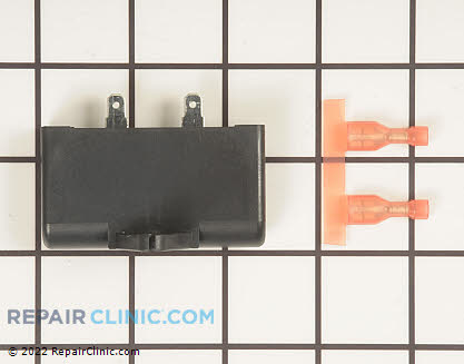
The part you need is wh49X10041

    My friend Ryan had a comment recently in my forum:

    I am going to give some estimated stats on what I have experienced over the past 3-4 years. Note that this is only out of warranty stats because if it is in warranty I replace the motor without hesitation.Also this may not reflect what other tech may be seeing.

    I have seen about 50-60 motor related problems with these washers.

    About a dozen or so fuses blown. Replacing the fuse put them back to work with no more problems. Note that the fuse is not going to be on the models being made now.

    I have had to replace 3 motors because the fault wouldn't clear or it came back.

    I had one fuse that blew as soon as I put it on and I believe the motor was bad but the customer opted out of the repair.

    The rest I have cleared the code without any more problems.

    On the early models there was a problem that when the customer opened the lid when the shifter coil was in the middle of shifting from wash to spin it would hang in shifting mode. This would cause the coil to have 135 VDC the whole time the lid was opened. During normal operation the135 VDC is only on the coils for the first 18 seconds when the washer is changing from wash to spin mode.

    Naturally this would cause the shifter to fail. Then the motor will display the shifter failure code (4 flashes) and the washer will not wash properly.

    The new motors will not do this. This is not something that the customer done wrong because it is supposed to be ok to open the lid at anytime.

    As for the codes?

    Over the years I have grown to hate self-diagnostics on appliances, which is what the codes are more or less. Too often when I go on a service call for any appliance that is giving a self-diagnostics code the board that is doing the diagnostics is what the problem is to start with.
    (If this makes any sense).

    I don?t think the customer is doing anything wrong.

    Overall I like the design of this machine but they got some kinks they need to work out. Should have been worked out before they went on the market.

    For anyone else that may read this thread?

    Don?t just clear the code. See what the code stands for and check what ever the code says is bad. If it doesn?t seem to be bad clear the code. If it seems to be bad, replace it then clear the code.

    For example if it is the lid switch code check the lid switch and if the lid switch is ok clear the code. If the code comes back the motor is bad.

    @