
The procedure works for both Toyota Avalon and 4 runner model:-----------
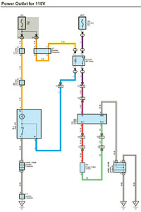
For wiring.
Click this link:---
-----------------------------
---------------------------------
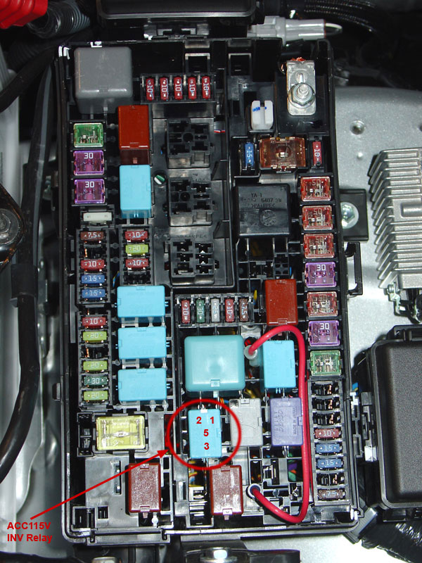
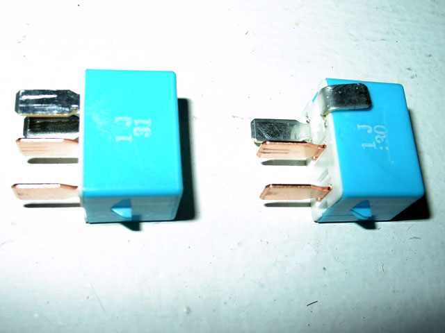
First, open the engine room relay/junction box and pull out the ACC 115V INV Relay. Pins #1 & #2 are the coil side of the relay. Pins #3 & #5 are the switch side of the relay. The upper left pin is #2. That is where 12v positive is needed to activate the coil if the dash switch is depressed. Pressing the dash switch provides ground to pin #1. Currently pin #2 is provided 12v positive from the IG1 fuse which is not active until the ignition switch is in the on position.
----------
We need to change that so that 12v positive can be sent to pin #2 anytime (with the vehicle off).
Bend pin #2 so that it no longer inserts into its usual location.
Bend pin #2 so that it no longer inserts into its usual location.
---------------
Take a short piece (approx 7") of 14 gague wire and crimp on a fully insulated female quick disconnecting terminal with a 0.187" tab. Do not use a standard 0.250" tab disconnect because it will not fit tightly enough. Connect the disconnect to the top prong of the relay (the one you just bent).
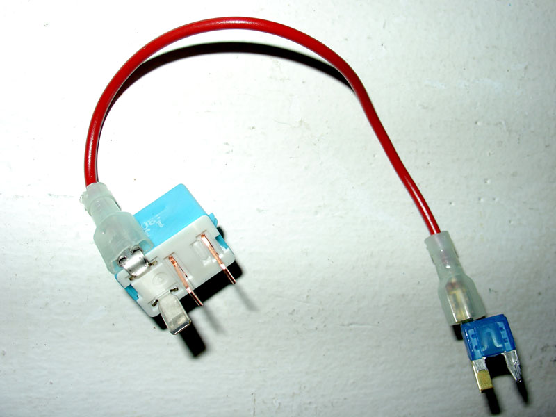
Run the other end of the wire to pin #2, the left side, of the AC 115V INV 15amp fuse. This fuse has power all the time. I used a fuse tap which wraps tightly around one leg of the fuse and has a male tab on top. Again, use a crimp on type fully insulated female quick disconnecting terminal to connect the wire to the fuse tap.

Now on to the dash switch and driver side relay/junction box.
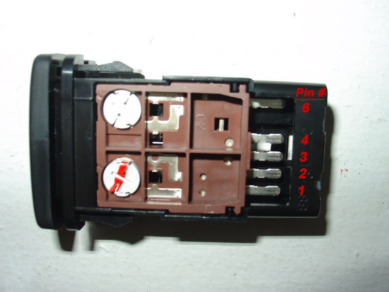
Pin #6 (yellow wire - red stripe) of the AC 115V switch is where 12v positive power is needed to activate the indicator light if the dash switch is depressed and the inverter is operating. Pressing the dash switch brings ground from pin #3 (white wire - black stripe) to both the ground side of the indicator bulb and to pin #4 (blue) of the dash switch. Additionally, pin #4 passes ground on to the negative side of the coil on the AC 115V INV relay.
Currently pin #6 (yellow wire - red stripe) on the dash switch gets it's 12v positive power from the IG1 fuse which, as you know by now, is not active until the ignition switch is in the on position. We need to change that so that 12v positive can be sent to pin #6 anytime (with the vehicle off). This part of the modification accomplishes that.
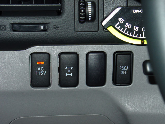
The switch itself looks like this:---
------------
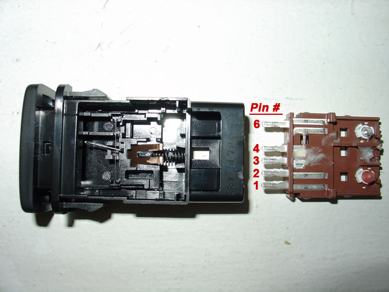
The inside of switch looks like this:---
------------------
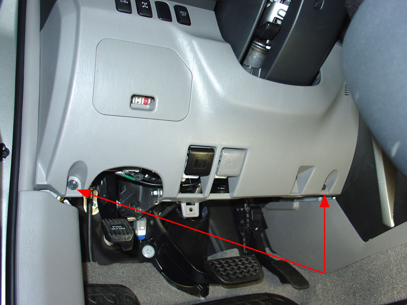
Remove driver side lower finish panel for access to driver side interior relay/junction box.
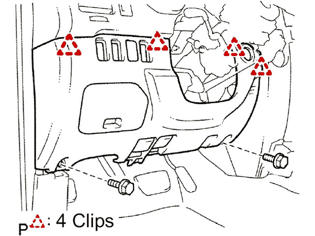
Start out by disassembling the lower dash area as we need access to the driver side interior relay/junction box. To access this area, first remove the two 10mm bolts holding the lower finish panel on. Pull the panel straight out to disengage 4 plastic clips still holding it on. The trim ring around the key hole will just pop out on it's own as you are doing this. Remove the wire harnesses attached to each of the switches located on the back side of this panel. Also on the back right side of this lower finish panel is the room temperature sensor harness (cooler thermistor), detach this from the panel as well. You may leave the fuel door release and the hood release handles attached to the panel. The panel can be lowered to the floor now.
Start out by disassembling the lower dash area as we need access to the driver side interior relay/junction box. To access this area, first remove the two 10mm bolts holding the lower finish panel on. Pull the panel straight out to disengage 4 plastic clips still holding it on. The trim ring around the key hole will just pop out on it's own as you are doing this. Remove the wire harnesses attached to each of the switches located on the back side of this panel. Also on the back right side of this lower finish panel is the room temperature sensor harness (cooler thermistor), detach this from the panel as well. You may leave the fuel door release and the hood release handles attached to the panel. The panel can be lowered to the floor now.
Remove driver side panel:---
----------
Pull to release 4 clips shown:--
---------------
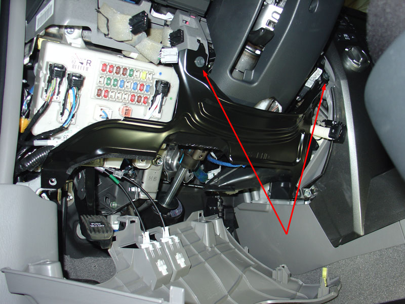
Remove lower bracket:
Remove two 10mm bolts holding the metal bracket around the bottom of the steering column. Disengage the 2 claws and remove the instrument panel lower left hand bracket. Set bracket aside.
Remove two 10mm bolts holding the metal bracket around the bottom of the steering column. Disengage the 2 claws and remove the instrument panel lower left hand bracket. Set bracket aside.
instrument panel bracket.
------------------
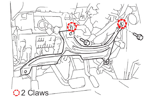
pull two claws.---------------
Make a jumper wire by taking a 3 inch piece of 14 gauge wire and crimping on a .250" spade solderless terminal to each end. On one of the ends, include a 9" length of 18 gauge wire as well.
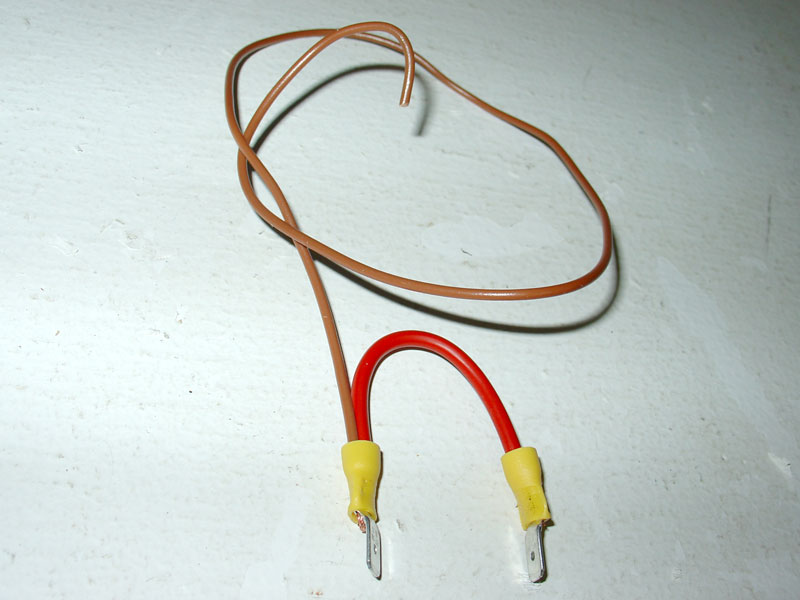
Jumper wire which will replace
the DC SKT Relay
the DC SKT Relay
-----------------
We will now perform the constant 12v power mod. Remove the DC SKT Relay by pulling it straight out firmly.
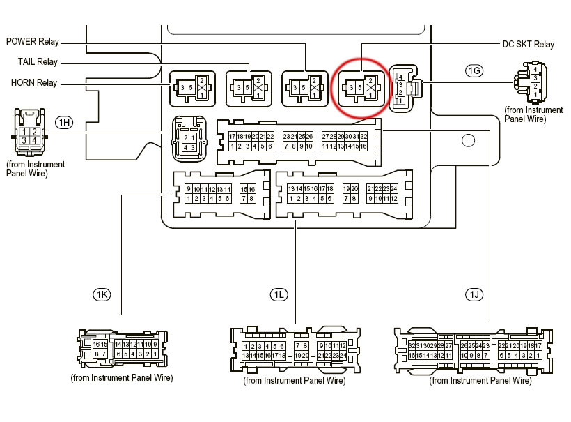
Insert one of the spade ends of the jumper we just made into the power outlet relay socket #3 and the other end to socket #5. Sockets #3 and #5 are the only places a standard .250" spade soderless terminal will fit, so you won't have any trouble identifying where to insert the jumper wire. You will now have 12v power full time to both the front and cargo area 12-volt auxiliary power points.
Now the 9" length of 18 gauge wire that is attached to one prong where the DC SKT relay was is getting constant power from the 15 amp Power Outlet fuse. We will use that to supply full time power up to the AC 115V dash switch. Cut the wire going to pin #6 (yellow wire - red stripe) on the AC 115V switch. These wires are wrapped in foam to prevent abrasion, so somewhere in the middle tear some of the foam off to expose the wire we need to cut. Now that the wire is cut in half, tape off the side coming from the upper dash area. Splice the wire coming from the DC SKT relay into the switch side of the yellow with red stripe wire. Use heat shring tubing or electrical tape to finish it off.
Now the 9" length of 18 gauge wire that is attached to one prong where the DC SKT relay was is getting constant power from the 15 amp Power Outlet fuse. We will use that to supply full time power up to the AC 115V dash switch. Cut the wire going to pin #6 (yellow wire - red stripe) on the AC 115V switch. These wires are wrapped in foam to prevent abrasion, so somewhere in the middle tear some of the foam off to expose the wire we need to cut. Now that the wire is cut in half, tape off the side coming from the upper dash area. Splice the wire coming from the DC SKT relay into the switch side of the yellow with red stripe wire. Use heat shring tubing or electrical tape to finish it off.
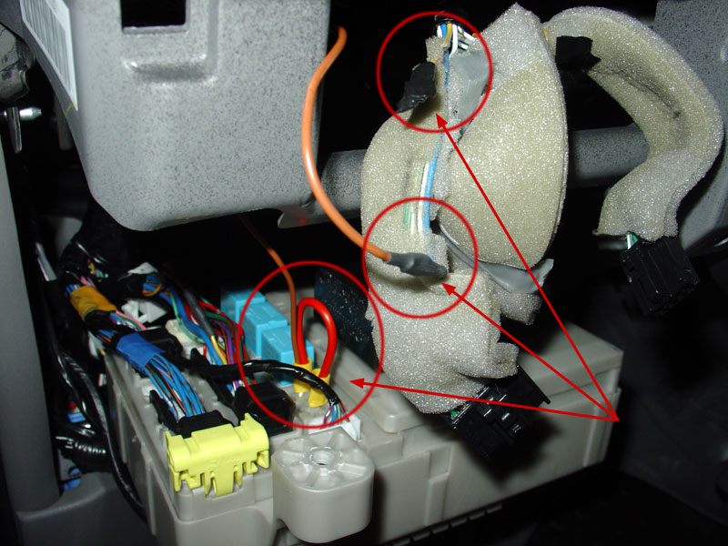
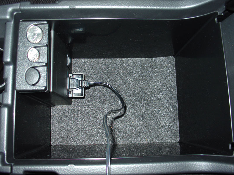
Jumper in place
and connected to switch
and connected to switch
Put the junction box, switches, and dash back together. Now with the key off test that the the 115V and 12V power outlets all have constant 12V power.
And if you really want to keep the factory look, you can always just wire up your own inverter in the factory location. The red arrows indicate the factory wire connector and the bolt locations.
And if you really want to keep the factory look, you can always just wire up your own inverter in the factory location. The red arrows indicate the factory wire connector and the bolt locations.

Remove your cargo mat.
2. Remove the plastic trim piece that covers the floor, at the back of the truck. It's 4 or 5 screws and then it's snapped on (real tight). I taped the head of a flat screwdriver and used that to pry it up. BE CAREFUL!
3. Remove the bridge between the 2nd row seats and cargo area. IIRC, it's just the two bolts holding down the cargo hooks.
4. Remove anything else that appears to be holding down the floor board. I don't remember if there is anything other than 1-3 above.
4. Slide out the cargo floor board (more carpet really). It comes out and goes back in easily.
5. Remove the upper left cargo net post (it's actually a clip). This is a little tricky at first. The very tip of that piece is actually a thin cap. Pull hard just on the very outer edge and it will pop up and release the clips inside. The whole thing then easily comes out.
6. Remove the cover of the 2nd row left passenger seat belt (where it attaches to the body). It just pops off....REALLY
7. Remove the bolt (the one revealed by removing the cover)holding the 2nd row left passenger seat belt to the body
8. Remove the screws/bolts holding the lower left interior panel in place. There are 2 on the floor, 1 in the box, 1 inside the cargo hook, and maybe a few others I don't recall. Look for them ALL. DON'T try to remove the box or cargo hook, just the screws. YOU CANNOT remove them from the outside.
9. Remove (or partially remove) the 2nd row left passenger door modling. You just need to lift up the part that's adjacent to the interior panel. The panel actually has clips that fit UNDERNEATH the molding. Don't worry, the molding is not glued, though it does feel like it is, at first. DON'T REMOVE the whole thing, just the little bit you need. That way it will be easy to get lined up correctly again.
10. Remove the 2nd row left passenger door sill. It just pops up.
11. OK, now there are about 5 or 6 clips holding the interior piece in place. I started prying them up from the back to the front. Once you get them all, the piece just lifts out.

No comments:
Post a Comment