
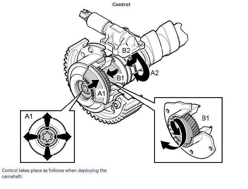
To go back to your original question, the holes in the camshaft have nothing to do with aligning the CVVT units. The CVVT units are "infinitely" adjustable in relation to the cam. The only thing that holds them to the cams is the center bolt torqued to a high value (120Nm).
The different shaped machined ends of the cams are for locating the cam sensor wheels. There is a horizontal slot that's offset slightly from center, and there is a beveled slot that comes out at an angle from it. The horizontal slot lines up two things. One, it lines up with the cam locking tool when installing and setting up the cams. Two, it lines up with the horizontal tabs in the cam sensor wheels. The angled slot lines up with the other. There is an intake and exhaust cam sensor wheel and they are marked "IN" and "EX" on them.
The block must be locked in place as do the cams. Volvo's special tool for the cams is(NNN) NNN-NNNNand the block pin is(NNN) NNN-NNNN The starter must be removed and the torx head plug behind it removed to install the pin. You turn the crank clockwise just past the alignment mark on the crank and the oil pump housing, insert the pin, and then turn the engine counterclockwise until it stops on the pin. The cams have to be locked together with the cam tool.
The CVVTS are actually pretty easy to set up once you know the trick. Volvos procedure in VIDA is confusing, but will get you there in a roundabout way. There's an easier way. Put the cam gears onto their respective CVVT units and put the outer screws in. Snug them up until they are just barely tight. Set the bolts up so they are in the CENTER of the long slots. Install them onto the cams with the center bolts. Snug up the bolt and then turn the CVVT unit clockwise until it stops. Then loosen the center bolt slightly and rotate the unit CLOCKWISE around until the timing marks line up. The CVVT units both need to be internally against their stop with the outer part of the CVVT clockwise in relation to the inner part.
Once the timing marks are lined up, tighten the center bolt up lightly and check to make sure the CVVT unit is still all the way clockwise. If it is, tighten the center bolt up to 120Nm.
Loosen the outer bolts on the cam gears slightly. Install the timing belt. the cam gears will move slightly on the CVVT units while you are doing this. That's fine. Set the tension on the timing belt tensioner. Once the belt is fully on, check to make sure your marks are still lined up.
The cam gear bolts should be somewhere floating near the center of the slots. Put the CVVT plugs in the CVVT units. Torque to 35Nm. Bringing those up to torque should make sure the CVVT unit is against it's internal stop again. The CVVT unit may move slightly in relation to the cam gears. This is fine, but the cam gear bolts should still be somewhere towards the center of the slots when you are done. They can be off center a bit, just so long as they aren't against the end of a slot. Now that the CVVTs are parked against their stop clockwise, you can tighten the outer cam gear bolts.
This is easier than Volvos left, right, move the slots to an end, set it two teeth before, set it one tooth before, do the hokey pokey mess. You end up at the same place with a much simpler to understand method. The whole idea of this is to end up with the CVVTs parked against their internal stop to the right and the cam gears to line up with the cam gear bolts somewhere in the slotted area with the timing marks lined up. The cam gear bolts can actually be anywhere in that slot as long as the timing marks are lined up and the CVVT unit is parked.
--------------
--------------
2. Just a rubdown with regular oil is fine.
3. Make sure all timing marks line up and you will be fine.
4. Use Volvo gasket sealer.
Here is a simplified version of it assuming the person who work on the car knows how to replace timing belt and adjust tensioner.
1.) Make sure all timing mark that can be used aligned to proper position as close as possible since it's out to begin with (oil pump and timing belt cover)
2.) Lock cam at the end of engine (cam locking tool).
3.) Remove timing belt
4.) Remove CVVT pulley
5.) loosen all 3 small bolts around sprocket so CVVT unit turns freely
6.) install center bolt with CVVT pulley(MAKE SURE BOLT IS DRY AND NO OIL) only finger tight
7.) turn pulley (clockwise) until pulley is 1 tooth beforealignment mark.
8.) Without disturbing the CVVT marking tighten center bolt to 120 newton meter (also tighten the 3 small bolt around the sprocket after the center bolt is tighten)
9.) torque outer cvvt cap to 35 newton meter
10.) re-installed timing belt and remove cam locking tool
NOTE: FROM 2nd step till 10 keep the cam lock

CVVT always on intake because cam sensors are always intake.
Slacken off, but do not remove, the (3) screws which secure the timing gear pulley to the variable valve timing (VVT) unit.
Press the variable valve timing (CVVT) unit / timing gear pulley on the camshaft.
Install the center screw which secures the variable valve timing (CVVT) unit to the camshaft and tighten slightly.
Turn the variable valve timing (CVVT) unit anti-clockwise as far as it will go.
Remove the center screw.
Position the upper timing cover.
Turn the timing gear pulley clockwise until the screws at the oval holes are in the limit position.
Continue turning clockwise until the timing gear pulley marking is 1 1/2 Cog before the marking on the upper timing cover
Note: Do not turn anti-clockwise during this procedure!
Check that the timing gear pulley is still in the limit position in the oval holes.
Tighten the center screw in the variable valve timing (CVVT) unit to 120 Nm (88 ft. lbs.) .
Check that the variable valve timing (CVVT) unit does not rotate when tightening.
Install and tighten the center plug to 35 Nm (26 ft. lbs.) .
Turn the variable valve timing (CVVT) unit clockwise to the limit position.
Turn the timing gear pulley so that the markings correspond.
For more help check fig:-- 
 ---------

-----------

----------
----------------
--------------

-----------------
-----------
-------------

No comments:
Post a Comment